Project Development
Assignment
Complete your final project. Track and document your progress. Create a final project slide in the archive according to the specifications provided.Learning Outcomes
Evaluate project plan.Apply time management techniques
Summarize and communicate the essence of a project
First Final Project Proposal
At the start of this program my first final project proposal was to make an LED phone case for an iPhone 6. I started with this idea because I thought I could incorporate a lot of weeks into it such as electronics design, computer controlled cutting, 3D moulding and casting, input and output devices, and networking and communication. Another reason I chose this project was because we needed to come up with one during the first week and I wasn't feeling that creative. So I just came up with this design to put something on my page. I knew down the road I would be changing my final project. However, here is the rough design of the LED phone case I came up with in Week 1.I continued with this final project in Week 2, Computer-Aided Design. I started out by developing some 2D designs in the program CorelDraw. I also made some basic designs for back covers on the case to allow someone to switch out the backing. I then moved onto 3D designs and used a program that was suggested by Wendy Neale called PTC Creo. Using this program I was able to mock up some rough designs of the phone, case, and backings for the LED phone case. These can be seen in my Week 2 page.
Second Final Project Proposal
Reaching Week 5, 3D Printing and Scanning, I had had some time to think about a final project some more. My proposal was to build a kegerator (fridge/keg) for home brewed beer as well as beer from breweries, see pictures below.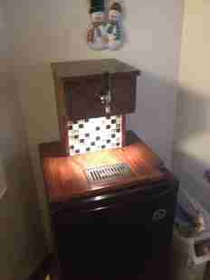
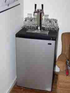
There are many great breweries in the great state of Alaska and to have their beer on tap in the home sounded like an awesome idea. My initial thoughts on the design were to buy a minifridge and modify it so that it could have a tap coming out the top of it. During the 3D printing and scanning week, I had actually built a custom tap handle to put on one of the taps. I would then use the skills learned in computer controlled machining to design some wood tower that would hold the beer lines. I would then need to have a fan control the air going up into the tower to keep the beer lines cool, as warm beer lines would produce a foamy beer out of the tap. Electronics design would have covered that in the control of the fan.
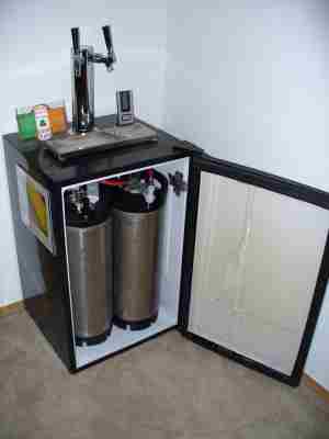
After doing more research, I ended up realizing that a chest freezer would be easier to convert rather than a mini fridge. They require less altering and you don't run the risk of hitting the refrigerant line while drilling out the top. And more importantly, you can hold more beer! Below are some pictures that I liked and would use some designs from them.
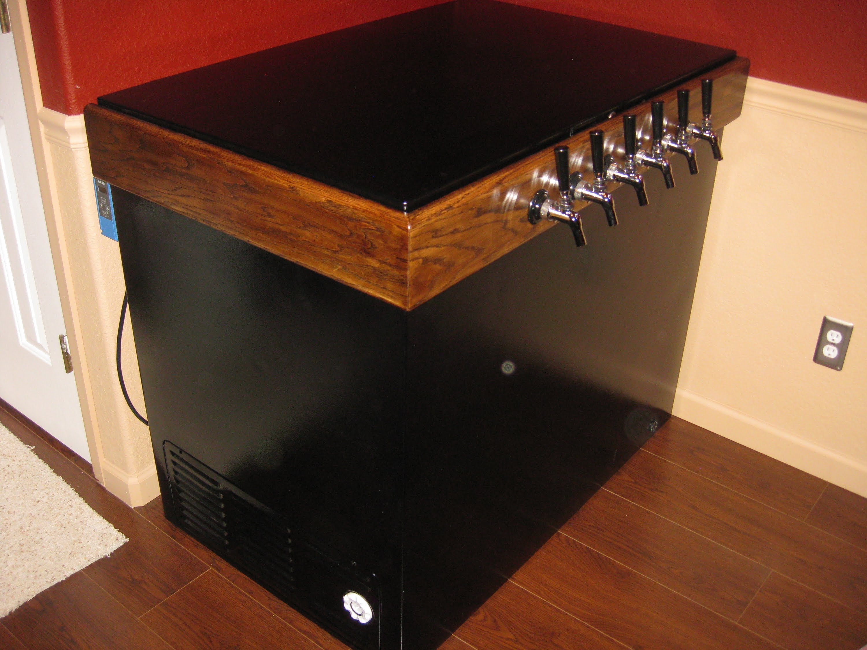
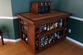
I was leaning more toward the second design, since I could have used my computer controlled machining skills in order to build some shelfing around it and tap tower on top. I would have then used my electronics design and production, as well as the networking and communication skills to develop boards that would keep track of the temperature. I would need it to not get too cold in the chest freezer and keep the freezer temperature around 44 degrees fahrenheit.
Final Final Project Proposal
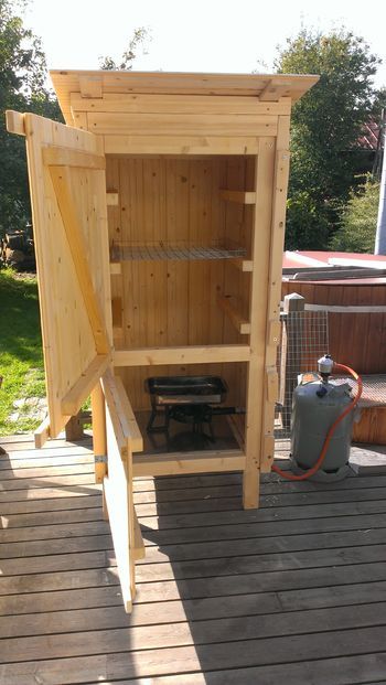
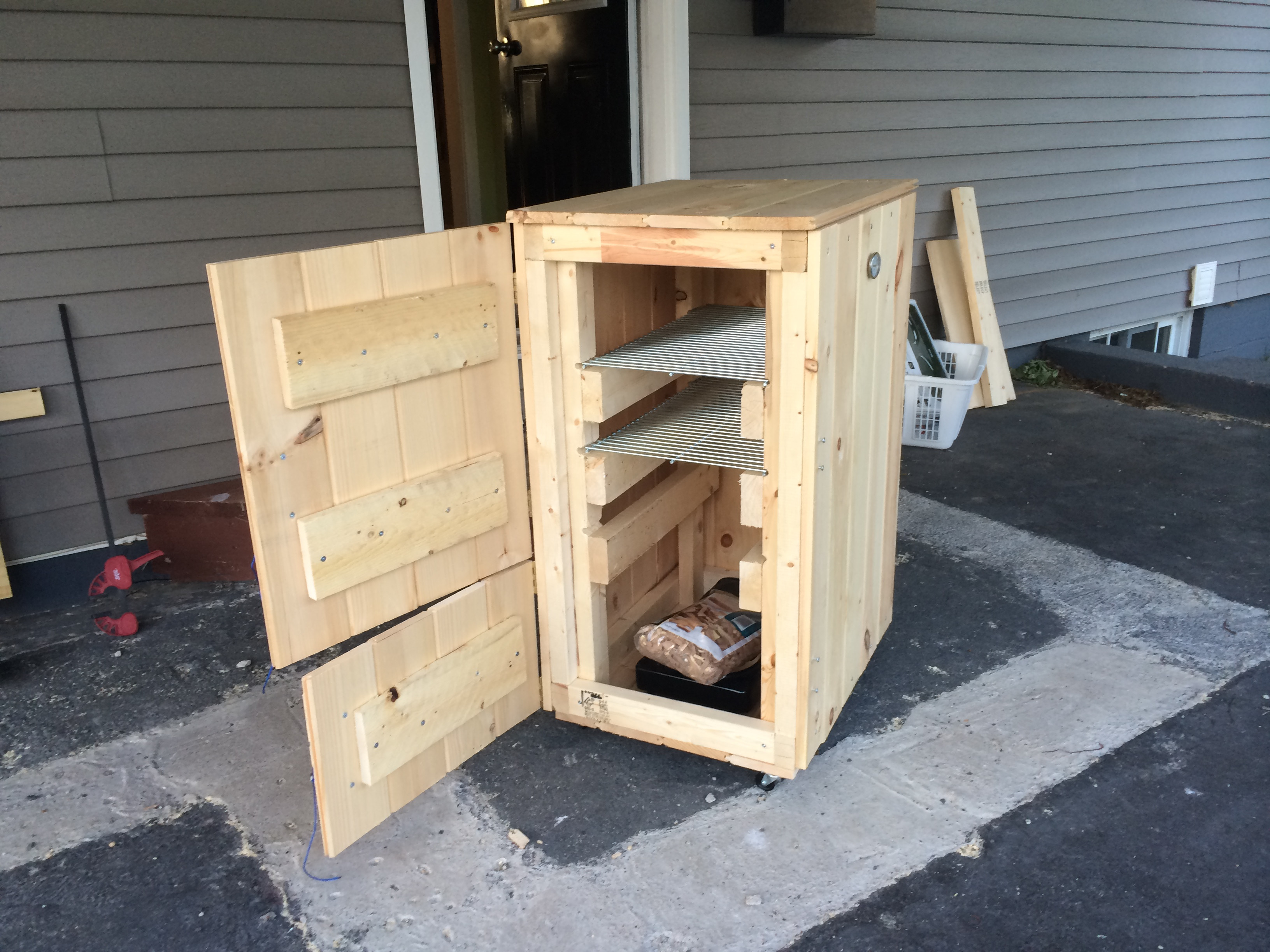
After some weeks of thinking about it more, I realized I would need to buy a lot of parts, especially plumbing for the inside. I decided to go against the keezer idea and move onto a project in which I wouldn't have to buy a lot of stuff and find a project in which I could make most of the parts. One evening talking with my brother and some friends while at dinner, my brother talked about wanting to make his own fish smoker. Talking with him more, I realized that could be a really cool final project and that I could make the first prototype since neither one of us had experience in making this type of product.Doing some research on DIY wood fish smokers, there are hundreds of designs out there of people building their personal smokers. A lot build them from tongue and groove pieces since they are easy to work with. However, I will be using my computer controlled machining skills to cut out panels on the ShopBot to put over a wooden frame. I will need some type of digital thermometer in order to keep track of the temperature on the inside of the smoker so it doesn't get too hot and start cooking the fish too quickly. I found a good person's design in which he uses a cheap food grade thermometer and powers it with an arduino. My plan is to build my own arduino and have an LCD communicating with the sensor and display it. If time permits I also want to build a 3D model and print out a housing for all of the electronics. Some of the designs I like so far:
Final Project Progress
Mechanical Design
3D Design
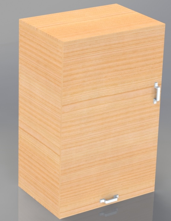
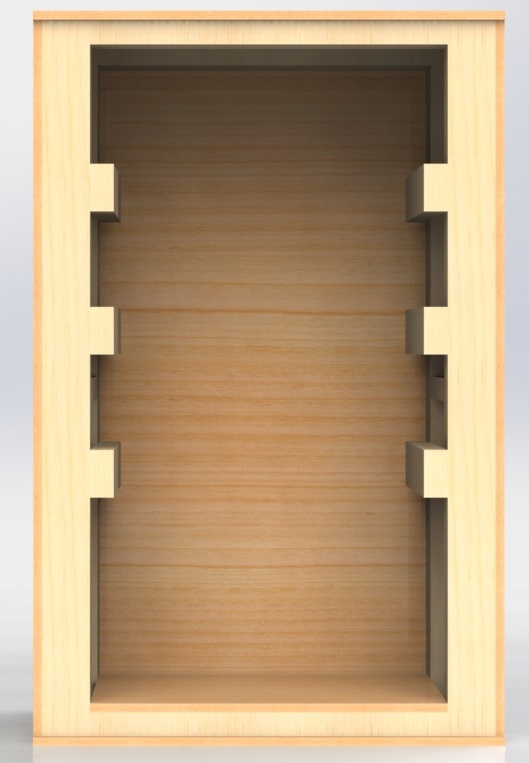
I first started by coming up with a design for the frame and the paneling for the fish smoker design. I used the program SolidWorks and came up with a frame assembly and full wood smoker design with the paneling. The frame will use 2"x4" boards and a door frame will use 2"x2". In the design I am going with 0.75" thick cedar (or pine, haven't decided yet on which one I want) plywood that will be used for the panelling. Below are the rendered images for the frame design and the full wood smoker design: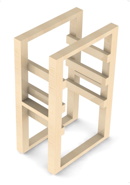
2D Designs for ShopBot
Once the SolidWorks Model was done, I had to make the drawings for the side panels and back panel so they could be cut out on the ShopBot. Using the process from Computer Controlled Machining week I made drawings in SolidWorks from the side panel and back panel parts. I learned in Week 7 that SolidWorks doesn't join the vectors together so I went into CorelDraw and import the drawing I had made in SolidWorks. Once in CorelDraw, I just went under "Object" and used the join curves option. This makes it so the drawing is one solid curve.3D Printing
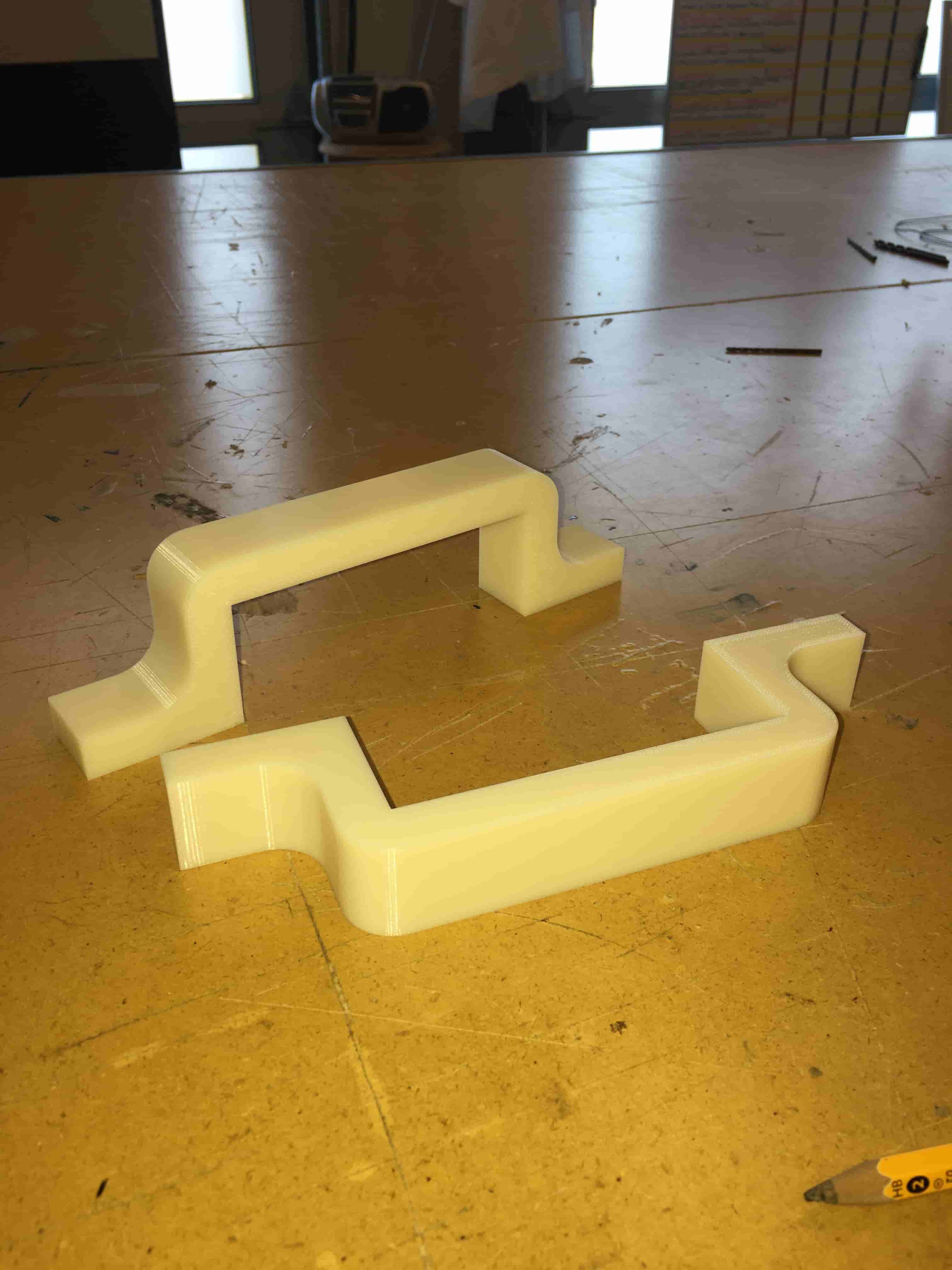
I wanted to have handles on each of the doors, so I modeled up a simple design in SolidWorks. After I was done with the model I saved it as a .stl file for the Dimension 3D printer. Below is a picture of the solid model and the printed parts after they were done.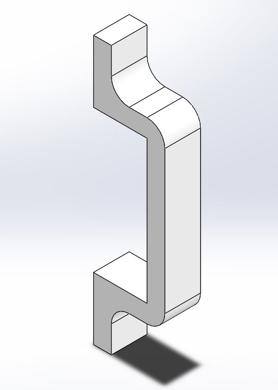
Electronics Design
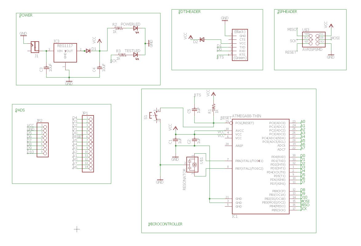
I needed a board that could control an LCD and Temperature Sensor. Since these libraries are fairly big I needed to upgrade to a bigger chip than the ATtiny chips. I found a well documented embedded circuit board that was built by Luciano called the Barduino. This design uses the ATMEGA328P chip with 32kB of flash. I based my board off of their design an made some minor adjustments:1. Upgraded the regulator to the 5V, 1A regulator.
2. Took out the second Schottky diode.
3. Put on the 5.5x2.1mm Power Jack, since we didn't have any of the smaller power adapters around our lab.
I designed the schmatic and board layout in Eagle. Below are the pictures of them:
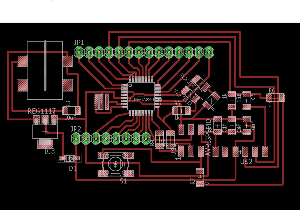
I was able to mill and stuff the board without much trouble and then did a smoke test. I was successful